| Brief Description | |
|---|---|
|
Files:
\examples\Processing\HDR_ImageComposition\HighDynamicRange\HDR_CRC_Bayer.vad |
 |
|
Default Platform: mE5-MA-VCL, imaFlex CXP-12 Quad |
|
|
Short Description HDR Algorithm According to Debevec and Malik and LDR Algorithm according to Reinhard et al. and Fattal et al.. |
|
High Dynamic Range (HDR) images reproduce a high range of luminosity. So both very dark and very bright details are combined in one image. With most photography techniques it is not possible to achieve this high range of luminosity with one single exposure time. So a HDR image is created from images with different exposure times. The HDR image can not be displayed directly on most displays. So a scaled reduction in brightness contrast to a Low Dynamic Range (LDR) image is necessary for displaying the HDR image. This procedure is also called tone mapping. In this VisualApplet example an HDR algorithm according to Debevec and Malik [Deb97] is implemented. The LDR algorithm is according to Reinhard [Rei02] and Fattal [Fat02]. In the following both algorithms will shortly be explained.
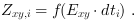
The pixel value  in an image i with pixel coordinates
 and
and
 can be expressed as a function of the irradiance value
  and
exposure time
and
exposure time  :
:
When we define  it follows:
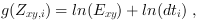
where we call  the response curve.
It relates the pixel value
the response curve.
It relates the pixel value
 for exposure time
 to the scene irradiance
 .
.
 is assumed to be constant for every pixel.
Knowing
is assumed to be constant for every pixel.
Knowing  and
and
 ,
,
 can be calculated with singular value decomposition
method [Deb97].
An HDR image can now be created using the following expression [Deb97]:
can be calculated with singular value decomposition
method [Deb97].
An HDR image can now be created using the following expression [Deb97]:
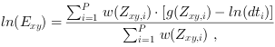
其中  are the logarithmic irradiance values (base
 ) on pixel x,y in the
resulting HDR image. For color images
) on pixel x,y in the
resulting HDR image. For color images  are the red, green
and blue values
(
are the red, green
and blue values
( ,
,
 and
and
 ).
That is, Equation 34 has to be separately calculated for red, green and blue values.
).
That is, Equation 34 has to be separately calculated for red, green and blue values.
 is the number of exposures.
In Equation 34
is the number of exposures.
In Equation 34
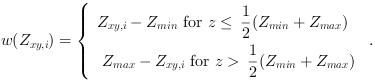
 is a weighting function:
To display the HDR image a reduction in brightness contrast is necessary. According to Reinhard et al. [Rei02] the LDR luminance
 can be calculated as:
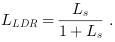
Here  is the scaled HDR luminance:

The parameter  adjusts the brightness of displayed LDR image.
Typical values are between 0.09 and 0.72 [Rei02]. The so called relative "world" luminance
adjusts the brightness of displayed LDR image.
Typical values are between 0.09 and 0.72 [Rei02]. The so called relative "world" luminance
 is calculated from HDR colors:
 ,
,
 and
and
 :
:

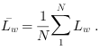
The mean value  is in this example calculated as
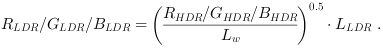
According to Fattal et al. [Fat02] the LDR color components
 ,
,
 and
and
 can now be reconstructed as
The LDR image values  for grayscale images for output on display can be calculated as:
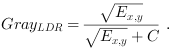
Here  is a result of HDR processing according to Equation 34.
 is a parameter constant which can be used for adaption of brightness in the output image.
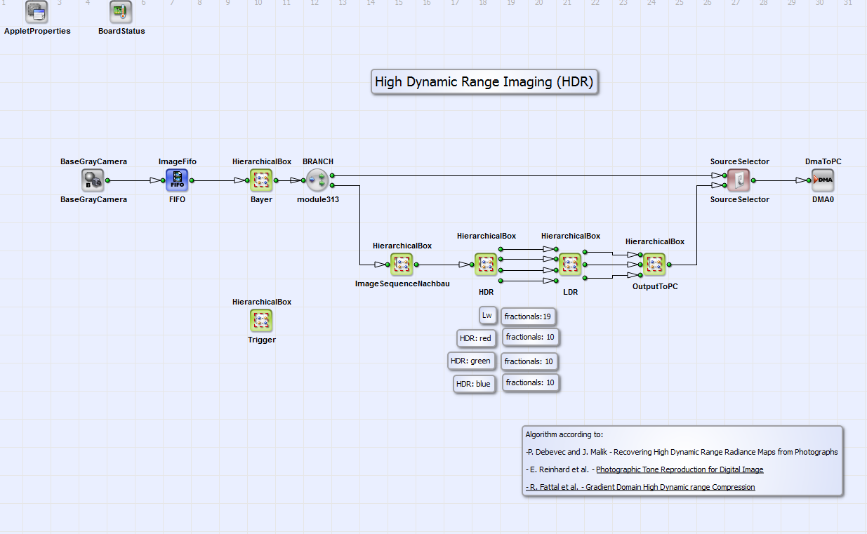
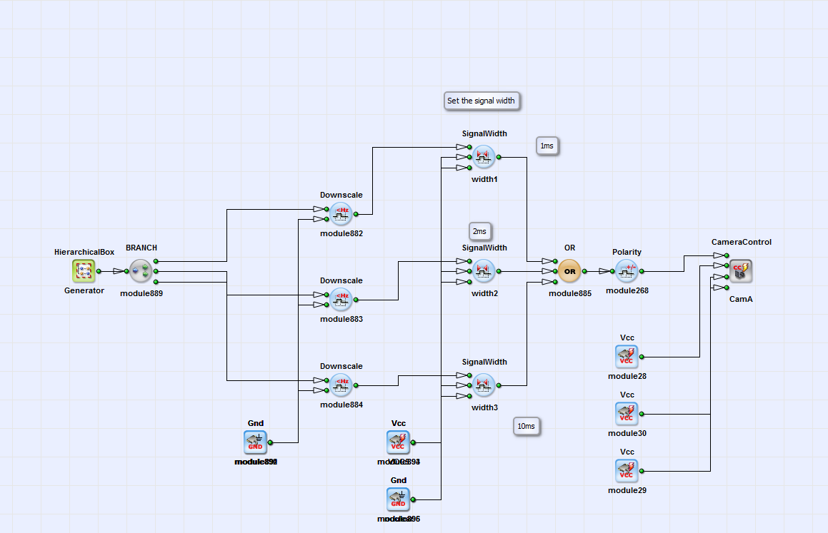
The HDR/LDR algorithm for filming scenes with very wide luminosity scale with very dark and very bright objects is implemented in VisualApplets for grayscale ("HDR_CRC_Gray.vad"), Bayer ("HDR_CRC_Bayer.vad") and color ("HDR_CRC_Color.vad") camera images. An image is transferred to PC in which every object of the scene is displayed properly. The basic structure of the design "HDR_CRC_Bayer.vad" is shown in Fig. 345. All examples follow the same principle. For a Bayer pattern raw image the red, green and blue values for every image pixel are calculated in the HierarchicalBox Bayer with a Bayer5x5Linear operator. This box is only content of the example "HDR_CRC_Bayer.vad". In the box ImageSequence a sequence of three images is buffered. The three images should have three different exposure times for HDR-LDR processing. The exposure times should be chosen that way that every image pixel is at least in one image of the exposure sequence neither under nor over exposed. You can set these times with the operators SignalWidth width1 to width3 in the HierarchicalBox Trigger (see Fig. 346). Please note that the time scale is system clock ticks of 8 ns. The operator Generate-Period has to be set at least to a value greater than the longest time of the operators SignalWidth width1 to width3. Please read in addition the minimum period length for operator Generate-Period in your camera manual. The three images are combined using the HDR algorithm according to Debevec and Malik [Deb97] described above. It is implemented in the HierarchicalBox HDR (Fig. 345). For the grayscale, Bayer and color images the implementation is equivalent. The LDR algorithm is implemented in LDR. The implementation for color/Bayer images and grayscale images is different (see sections and ). The colors of the resulting RGB image are merged in the HierarchicalBox OutputToPC. This box does not exist in the example "HDR_CRC_Gray.vad". The operator SourceSelector gives the opportunity to select the DMA transport of either the processed HDR-LDR image or the (Bayer demosaiced) camera image.
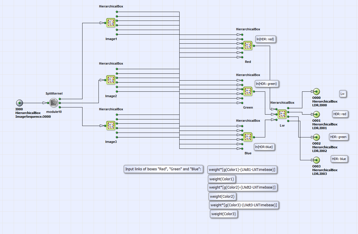
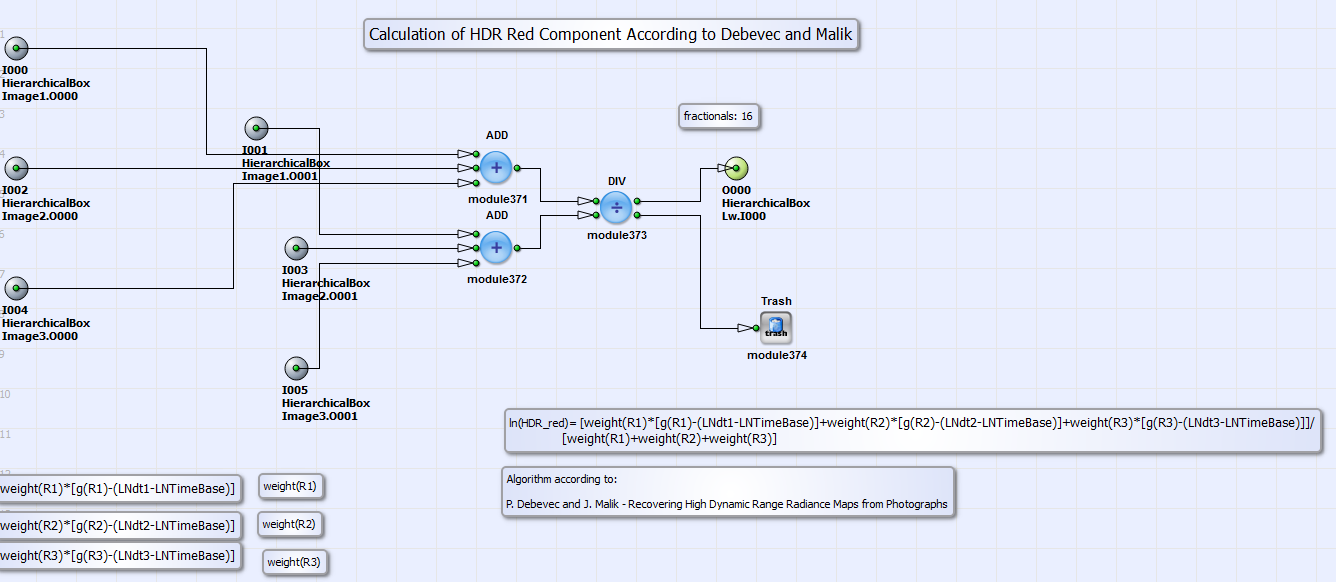
In Fig. 347 you can see the content of the HierarchicalBox HDR. For the three images of the buffered
image sequence the summands of the nominator
 and denominator
  of Equation 34 are calculated
for images one to three (HierarchicalBox Image1 to Image3) for the colors red, green and blue separately.
of Equation 34 are calculated
for images one to three (HierarchicalBox Image1 to Image3) for the colors red, green and blue separately.
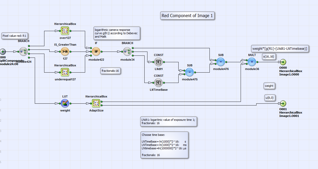
In Fig. 348 you can see this calculation for the color red for image 1 (in the HierarchicalBox 红色
in the box Image1) as an example. All colors for all images are processed the same way. The logarithmic values of the camera response curve
(CRC) are assigned
to the (red/green/blue) pixel values with a lookup table in the HierarchicalBox over127 if pixel value is higher than 127 or in box
underequal127 if the pixel value is less equal than 127. The content of these lookup tables gO127 and g_ueq_127 for the
colors red, green and blue can be calculated with the Matlab program modules "HDR_CRC.m", "sample.m" and "gsolve.m" (under
\examples\Processing\Advanced\HighDynamicRange\), which
are based on the code of Debevec and Malik [Deb97] and partially on the example of M. Eitz [Eit07].
Please read the short manual in "HDR_CRC.m" for further instructions how to use the code.
With the CONST operator LNdt1
(and analog LNdt2 and LNdt3 for images 2 and 3)
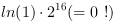
the logarithmic (base: e) value of the exposure time can be set. Please note, that this value has to be multiplied by
 because of 16 fractional bits.
The corresponding time base can be chosen by the parameter LNTimeBase. Values of
because of 16 fractional bits.
The corresponding time base can be chosen by the parameter LNTimeBase. Values of
 ,
,
 或
或
 set the time scale to seconds, milliseconds or
microseconds. In the lookup table weight in Fig. 348 the weighting function of Equation 35
is implemented. With the Matlab program modules "HDR_CRC.m", "sample.m" and "Weight.m" the weighting table "Weights.txt"
can be created. Please read also the short manual in "HDR_CRC.m"
(or "HDR_CRC_Gray.m" for grayscale images) for further instructions. Final outputs of the HierarchicalBox 红色 (and analog 绿色 and
蓝色) in box Image1 (and analog Image2 and Image3) are then
set the time scale to seconds, milliseconds or
microseconds. In the lookup table weight in Fig. 348 the weighting function of Equation 35
is implemented. With the Matlab program modules "HDR_CRC.m", "sample.m" and "Weight.m" the weighting table "Weights.txt"
can be created. Please read also the short manual in "HDR_CRC.m"
(or "HDR_CRC_Gray.m" for grayscale images) for further instructions. Final outputs of the HierarchicalBox 红色 (and analog 绿色 and
蓝色) in box Image1 (and analog Image2 and Image3) are then
 and
and
 .
.
Coming back to Fig. 347 as content of box HDR.
The calculation of the logarithmic values of the HDR color components
 ,
,
 and
and
 according to
Equation 34 is performed in the boxes 红色, 绿色 and 蓝色. A summation over all components of nominator
according to
Equation 34 is performed in the boxes 红色, 绿色 and 蓝色. A summation over all components of nominator
 and
denominator
and
denominator  values and final division is implemented here
(see color red in Fig. 349 for example).
values and final division is implemented here
(see color red in Fig. 349 for example).
The box Lw in Fig. 347 contains the calculation of the HDR color values
 ,
,
 and
and
 from their logarithmic values.
The exponential function is implemented with lookup tables. The relative "world" luminance "Lw" is then calculated from
the HDR color components according to Equation 38.
Its mean value according to Equation 39 is calculated in box Lw_d in the module LDR (see basic design structure Fig.
345). The whole content of LDR is shown in Fig. 350.
from their logarithmic values.
The exponential function is implemented with lookup tables. The relative "world" luminance "Lw" is then calculated from
the HDR color components according to Equation 38.
Its mean value according to Equation 39 is calculated in box Lw_d in the module LDR (see basic design structure Fig.
345). The whole content of LDR is shown in Fig. 350.
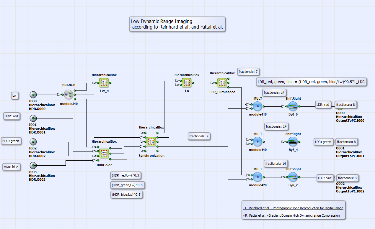
The module Ls contains the calculation of the scaled luminance according to Equation 37 as division of relative "world" luminance and its mean
value multiplied by a "brightness parameter" a. By changing this parameter value you can change the brightness of the final processed image. You can find
appropriate values for this parameter in the comment box in the VA design or in case of deeper interest in [Rei02]. LDR_Luminance calculates
the LDR luminance according to Equation 36. This value is finally multiplied with the outputs of the
HierarchicalBox HDRColor  ,
,
 and
and
 for color components red, green and blue separately. The results are then the LDR color components red, green and blue
[Fat02] of the processed output image.
The content of HierarchicalBox LDR for grayscale images is shown in Fig. 351.
for color components red, green and blue separately. The results are then the LDR color components red, green and blue
[Fat02] of the processed output image.
The content of HierarchicalBox LDR for grayscale images is shown in Fig. 351.
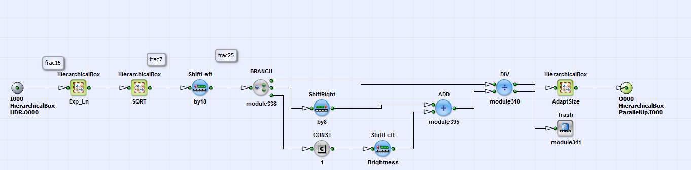
In the HierarchicalBox Exp_Ln  is calculated from
its logarithmic value
is calculated from
its logarithmic value  as result of HDR processing (Equation 34).
In the box SQRT the square root is extracted according to the algorithm in section . The result is divided by itself
plus
as result of HDR processing (Equation 34).
In the box SQRT the square root is extracted according to the algorithm in section . The result is divided by itself
plus  . The value of
 and with it the brightness of the output image can be set with the operator
ShiftLeft_Brightness.
and with it the brightness of the output image can be set with the operator
ShiftLeft_Brightness.
